Quantcast
Channel: Radio Astronomy – rtl-sdr.com
Viewing all 113 articles
Browse latest View live

Live: Perseids Meteor Shower with RTL-SDR

$
0
0

The annual Perseids meteor shower is peaking right now (this Wednesday and Thursday), and with the right equipment (and location) you can detect these meteors with an RTL-SDR dongle and appropriate antenna. When a meteor enters the atmosphere it leaves behind a brief trail of ionized air which is highly reflective to RF signals. These trails can reflect carrier waves from distant transmitters towards your antenna, allowing you to detect a meteor entering the atmosphere. This is called meteor scatter.

If you live in Europe, you can use the powerful Graves radar at 143.050 MHz as the transmitter. In other locations and the USA you can also use analogue TV broadcasts like in this post where the observer uses a TV tower in Canada. For Graves all you’ll need is a dipole antenna and perhaps LNA, but for TV transmissions you may need a directional Yagi antenna. More information can be found in our previous posts about meteor scatter and is this document.

But for now if you just want to observe others then currently there is this temporary live stream (now offline) shown below from Poland on YouTube and this always running live stream from the USA.

Equpment used by Reddit user Maxworm to detect Perseids meteors using the Graves radar: Dipole, LNA, Bias-Tee RTL-SDR.
Equipment used by Reddit user Maxworm to detect Perseids meteors using the Graves radar: Dipole, LNA, Bias-Tee and RTL-SDR.
Meteor detected by MaxWorm.
Meteor detected by MaxWorm

The post Live: Perseids Meteor Shower with RTL-SDR appeared first on rtl-sdr.com.


Creating a low cost Ozone Spectrometer out of RTL-SDR’s to measure mesospheric winds and tides

$
0
0

Over at the MIT Haystack Observatory in Westford Massachusetts, researchers O.B Alam and A.E.E Rogers have been working on creating a low cost ground based Ozone spectrometer out of RTL-SDR dongles (pdf warning). An Ozone spectrometer is used by scientists to measure the concentration, velocity and temperature of the ozone gasses in the mesosphere (50 – 85 km above the ground) and lower thermosphere (85 km+) at the Ozone line frequency of 11072.4545 MHz.

The spectrometer the researchers built consists of a satellite TV parabolic reflector dish with 46.72cm diameter, 9750 MHz LNBF, two Bias Tees, two 740 MHz high pass filters, two 8dB attenuators, a calibration pulse generator, an Intel NUC mini PC and three R820T RTL-SDR dongles.

RTL-SDR based Ozone Spectrometer block diagram from the MIT Haystack Observatory.
Photo of some of the components of the ozone spectrometer.

The post Creating a low cost Ozone Spectrometer out of RTL-SDR’s to measure mesospheric winds and tides appeared first on rtl-sdr.com.

Detecting Pulsars (Rotating Neutron Stars) with an RTL-SDR

$
0
0

The RTL-SDR has been used for some time now as an amateur radio astronomy tool. Radio astronomers Peter W East and GM Gancio have recently uploaded a paper that details their experiments with detecting Pulsars with an RTL-SDR (doc file).

A pulsar is a rotating neutron star that emits a beam of electromagnetic radiation. If this beam points towards the earth, it can then be observed with a large dish antenna and a radio, like the RTL-SDR. The abstract of the paper reads: 

This project sought to determine the minimum useful antenna aperture for amateur radio astronomers to successfully detect pulsars around the Hydrogen line frequency of 1420MHz. The technique relied on the collaboration with GM Gancio, who provided RTL SDR data of the Vela pulsar (B0833-45, J0835-4510) and others, collected with a 30m radio telescope. This data was processed to determine the achievable signal-to-noise ratio from which, the minimum useful dish size necessary for some effective amateur work, could be calculated. Two software packages were developed to do synchronous integration, a third to provide a power detection function and a fourth for spectrum analysis to recover pulsar rotation rate.

With their system the authors were able to detect and measure the rotation period of the Vela pulsar. Also, from their data they were able to estimate that the minimum dish aperture required to observe the Vela pulsar would be 6m, noting that the Vela pulsar is probably the strongest pulsar ever detected. They also write that by utilizing 5 RTL-SDRs to gather 10 MHz of bandwidth together with some processing that the minimum required dish aperture could be reduced to 3.5m.

The Vela pulsar pulse power integrated over a 50 second 100MB file, combining some 560 pulsar pulses
The Vela pulsar pulse power integrated over a 50 second 100MB file, combining some 560 pulsar pulses.

In addition to these Pulsar experiments, Peter has also uploaded new papers about improving his Hydrogen Line RTL-SDR Telescope (pdf), and has updated his paper on improving the frequency stability of RTL-SDR’s with air cooling (doc file). Peter found that the frequency stability of the RTL-SDR (with standard oscillator) could be significantly improved by adding heat sinks and aircooling them. The graph from his paper below summarizes his results.

Results from air cooling the RTL-SDR.
The air cooled and heatsinked RTL-SDRs
The air cooled and heat sinked RTL-SDRs

All of Peters papers can be found on his website at y1pwe.co.uk/RAProgs/index.html. He has many RTL-SDR radio astronomy related resources there, so check it out if you are interested.

The post Detecting Pulsars (Rotating Neutron Stars) with an RTL-SDR appeared first on rtl-sdr.com.

Radio Astronomy with an RTL-SDR, Raspberry PI and Amazon AWS IoT

$
0
0

Recently amateur radio astronomer Mario Cannistrà wrote in and showed us a link to his project. Mario has been doing some interesting experiments with an RTL-SDR that involve receiving emissions originating from the Sun, the planet Jupiter, and one of its moons Io.

Jupiter and its satellites like Io sometimes interact to create “radio storms” which can be heard from earth at frequencies between 3 to 30 MHz. The radio storms can be predicted and Mario uses the Windows software Radio Jupiter Pro to do this. This helps to predict when are the best times to listen for emissions. On his Raspberry Pi Mario has also written a python script that can do the predictions too. 

To make the radio emissions measurements, Mario uses an RTL-SDR dongle and upconverter together with rtl_power to gather FFT frequency power results and waterfall plots. To measure the emissions Mario writes that he keeps the frequency scan running for at least several hours a night with a Raspberry Pi as the receiving computer. For his antenna the low Jupiter frequencies necessitate a large 7 meter dipole tuned for receiving at 20.1 MHz.

For the Internet of Things side of the project, Mario envisions that several amateur radio astronomers around the world could run a similar setup, with all sharing the data to an Amazon AWS data storage server. Mario has already written software that will do the scan and automatically upload the results to the server. To participate you just need to write to him to receive the AWS IoT authentication certificate files.

Some example Jupiter spectographs stored on the AWS server can be found at http://jupiter-spectrograms.s3-website.eu-central-1.amazonaws.com/?prefix=Jupiter/20160130/.

Mario's setup including RTL-SDR dongle, upconverter and Raspberry Pi.
Mario’s setup including RTL-SDR dongle, upconverter and Raspberry Pi.
Overall design of the receiver and IoT side.

The post Radio Astronomy with an RTL-SDR, Raspberry PI and Amazon AWS IoT appeared first on rtl-sdr.com.

Radio Astronomy Tool rtl_power_fftw Updated

$
0
0

The rtl_power program allows you to use the RTL-SDR to perform a power scan over an arbitrarily large portion of the frequency spectrum (within the RTL-SDR’s supported frequency range) by hopping over ~2 MHz swaths of bandwidth. The updated rtl_power_fftw software was originally written by Klemen Blokar and Andrej Lajovic and is an update over the regular rtl_power program. It uses a faster FFT processing algorithm and has several other enhancements that make it more useful for radio astronomy purposes.

Recently Mario Cannistrà has released a new version of rtl_power_fftw which has several additional improvements applied. He intends to use it in his RTL-SDR based radio astronomy IoT project which is presented on his Hackster.io blog. He writes:

I added the following command line parameters:

  • -e param for session duration
    this allows to specify the recording duration in sec, mins… etc just like it was possible with rtl-power
  • -q flag to limit verbosity
    this will allow the various printouts to happen only the first time and not on every scan
  • -m param to produce binary matrix output and separate metadata file
    this will get a file name (no extension) and use it to store the power values in binary format within a .bin file + a metadata text file with .met extension

Summary of my requirements:

  • I wanted to leverage the ability of rtl-power-fftw to specify N average values to integrate for less than 1 second when needed. Plus running multi-MHz scans and storing for several minutes.
  • I wanted to use a binary format instead of the .csv one in order to obtain the smallest possible size since I’m logging all the night long (CSV’s blank delimiters and decimal dots were wasting my precious microSD space)
  • keep high the precision on decimal digits saving float values (could be important for other usages)
  • obtain a complete stream of binary values representing all the bins for each scan, one scan after the other, in a matrix like organization
  • …that would allow me to plot the waterfall extremely fast with gnuplot
  • …and then add specific annotations and file properties/metadata in a more convenient way using python
Example rtl_power_fftw output: A scan of Jupiter's radio emissions.
Example rtl_power_fftw output: A scan of Jupiter’s radio emissions.

The post Radio Astronomy Tool rtl_power_fftw Updated appeared first on rtl-sdr.com.

Software De-Dispersion of RTL-SDR Pulsar Data

$
0
0

Back in September 2015 we posted about how radio astronomers Peter W East and GM Gancio were able to use an RTL-SDR dongle for the radio astronomy task of detecting pulsars. A pulsar is a rotating neutron star that emits a beam of electromagnetic radiation. If this beam points towards the earth, it can then be observed with a large dish antenna and a radio, like the RTL-SDR. 

More recently they published a new paper titled “Software De-Dispersion of RTL-SDR Pulsar Data” (pdf).  De-dispersion is a technique that allows very weak signals to be extracted from the background noise. The introduction to the paper reads:

Data files produced by RTL SDR dongles can be folded directly for pulsar detection using software such as rapulsar.exe. Using simple I/Q vector averaging software, the data can be down-sampled by factors of more than 100 prior to folding and/or period search processing to speed up useful data extraction. Ideally, wide band RF data should be de-dispersed to optimise later search and folding processing. De-dispersion is normally carried out by time adjusting data sampled from RF filter banks before combination. This note describes how data already digitised from the RTL SDR can be spectrum analysed or filtered using the FFT algorithm. Two methods are discussed, one summing power with some down-sampling; the second, a ‘coherent’ method that de-disperses the rtlsdr.exe .bin data file and outputs a .bin-compatible file. Both accurately de-disperses the data offering an improved folded data SNR.

More information about radio astronomy with the RTL-SDR, pulsars and the associated software links can be found at Peter W East’s webpage http://y1pwe.co.uk/RAProgs/index.html.

The de-dispersion principle

The post Software De-Dispersion of RTL-SDR Pulsar Data appeared first on rtl-sdr.com.

Hydrogen Line Observation with an RTL-SDR

$
0
0

The RTL-SDR can be used for many interesting radio astronomy applications such as observing the Hydrogen line. Hydrogen atoms randomly emit photons at a wavelength of 21cm (1420.4058 MHz). Normally a single hydrogen atom will rarely emit a photon, but since space and the galaxy is filled with many hydrogen atoms the average effect is an observable RF power spike at 1420.4058 MHz. By pointing a radio telescope at the night sky and integrating the RF power over time, a power spike indicating the hydrogen line can be observed in a frequency spectrum plot.

On his website Steve Olney has been writing about his experiments and results with using an RTL-SDR to observe the hydrogen line. On his website he writes that he uses a 3M dish, with an LNA at the antenna to reduce the system NF, a hydrogen line tuned bandpass filter to remove out of band noise, 2 line amps to overcome coax loss, and finally a second LNA just before the RTL-SDR dongle to optimize the signal strength for the ADC. The dongle he uses has been modified to use a TCXO, and is aircooled via a PC fan. He also uses a modified version of the rtlsdr.exe IQ file recorder and his own custom GUI for controlling the RTL-SDR and antenna tracking mechanism.

His results show that he was able to detect the Hydrogen in the Large and Small Magellanic clouds. He also shows a method for converting the 8-bit IQ data down to 1-bit to save disk space, and shows that while some noise is added, the overall result is preserved.

See the related posts for other hydrogen line experiments with the RTL-SDR.

The 3M dish used for hydrogen line detection.
The fan cooled RTL-SDR used to detect the Hydrogen line.

The post Hydrogen Line Observation with an RTL-SDR appeared first on rtl-sdr.com.

Notes on Amateur Radio Astronomy for Beginners

$
0
0

RTL-SDR.com reader Jean Marie Polard (F5VLB) recently wrote in to let us know about a useful document that he has put together which covers beginners amateur radio astronomy. The document includes various introductions to the types of antennas and electronic tools often used in radio astronomy, the software used and an introduction to all the different types of observable objects. There are also a few mentions of the RTL-SDR dongle which is known to be a useful tool for amateur radio astronomy.

The document is available in pdf form in English, as well as in French. If you are looking at getting started in amateur radio astronomy then this is a good starting guide.

jean_ra

The post Notes on Amateur Radio Astronomy for Beginners appeared first on rtl-sdr.com.


IF Average SDR# Plugin Updated

$
0
0

The IF Average tool is a RTL-SDR compatible plugin for SDR# which allows you to plot an average of the current spectrum shown in SDR#. This is especially useful for radio astronomers who often need to average the spectrum for a long time in order to get a good plot of the Hydrogen Line. Recently the plugin was updated to support newer versions of SDR# and to upgrade some features. Daniel Kaminski, the author of the plugin writes:

I used ultrafast FFT which works on 4k to 512k bit space. With this plugin it is possible to average up to 64000000 samples in real time. XNA allows to shows the calculation results in real time.

To install the plugin you will need to install the XNA Framework 4.0 Redistributable first. Then copy the plugin files over to the SDR# folder and add the “magicline” to the SDR# Plugins.xml file.

The IF Average SDR# Plugin

The post IF Average SDR# Plugin Updated appeared first on rtl-sdr.com.

Building a Quad RTL-SDR Receiver for Radio Astronomy

$
0
0

Amateur radio astronomer Peter W East has recently uploaded a new document to his website. The document details how he built a quad RTL-SDR based receiver for his radio astronomy experiments in interferometry and wide-band pulsar detection (pdf – NOTE: Link Removed. Please see his website for a direct link to the pdf “Quad RTL Receiver for Pulsar Detection”. High traffic from this post and elsewhere has made the document go offline several times). Interferometry is a technique which uses multiple smaller radio dishes spaced some distance apart to essentially get the same resolution a much larger dish. Pulsars are rapidly rotating neutron stars which emit radio waves, and the strongest ones can be observed by amateur radio telescopes and a receiver like the RTL-SDR.

The Quad receiver has four RTL-SDR’s all driven by a single TCXO, mounted inside an aluminum case with fans for air cooling. He also uses a 74HC04 hex inverter to act as a buffer for the 0.5 PPM TCXO that he uses. This ensures that the TCXO signal is strong enough to drive all four RTL-SDRs.

The Quad RTL-SDR with air cooling.

Whilst all the clocks are all synced to a single master clock, synchronisation between the RTL-SDR’s is still difficult to achieve because of jitter introduced by the operating system. To solve this he introduces a noise source and a switch. By switching the noise source on and off, correlation of the signal data can be achieved in post processing.

Noise Source and Switch Calibration Unit.
How correlation with the pulsed noise source works.

In the document Peter shows in detail how the system is constructed, and how it all works, as well as showing some interferometry results. The system uses custom software that he developed and this is all explained in the document as well.

The post Building a Quad RTL-SDR Receiver for Radio Astronomy appeared first on rtl-sdr.com.

Radio-Sky Spectrograph now supports the SDRPlay

$
0
0

Radio-Sky Spectrograph is a radio astronomy software program that integrates data over long periods of time and displays it as a waterfall. It is described by the author:

Radio-Sky Spectrograph displays a waterfall spectrum. It is not so different from other programs that produce these displays except that it saves the spectra at a manageable data rate and provides channel widths that are consistent with many natural radio signal bandwidths. For terrestrial , solar flare, Jupiter decametric, or emission/absorption observations you might want to use RSS.

Radio Sky Spectograph is compatible with the RTL-SDR via an intermediary program called RTL Bridge, and now it is also compatible with the SDRplay via another intermediary program written by Nathan Towne called SDRplay2RSS

In previous posts we showed how some amateur radio astronomers were able to capture noise bursts from the sun and from Jupiter with an RTL-SDR. In the SDRplay software release post and documentation that comes with the software Nathan shows how he was able to capture solar emissions and Jupiter bursts with the SDRplay.

SDRPlay2RSS
SDRPlay2RSS
Solar emissions received with the SDRplay and Radio-Sky Spectograph.
Jupiter Noise Bursts with the SDRPlay and Radio-Sky Spectrograph.

The post Radio-Sky Spectrograph now supports the SDRPlay appeared first on rtl-sdr.com.

New SDR# Plugin: Radio-Sky Spectrograph Data Stream

$
0
0

Edit: If you downloaded an older version of the plugin please note that it has now been updated. The update fixes some stability issues which would previously hang SDR#. The updated .dll file can be downloaded directly from https://goo.gl/VQlH9E.

Radio-Sky Spectrograph is a radio astronomy software program which is often used together with the RTL-SDR or other similar SDRs. It is best explained by the author:

Radio-Sky Spectrograph displays a waterfall spectrum. It is not so different from other programs that produce these displays except that it saves the spectra at a manageable data rate and provides channel widths that are consistent with many natural radio signal bandwidths. For terrestrial , solar flare, Jupiter decametric, or emission/absorption observations you might want to use RSS.

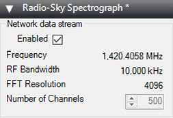
Usually to interface an RTL-SDR with Radio-Sky Specrtograph a program called RTL-Bridge is used. However, now SDR# plugin programmer Alan Duffy has created a new plugin that allows SDR# to interface with Radio-Sky Spectrograph via a network stream. This allows it to work with any SDR that is supported by SDR# plugins. Alan Duffy writes:

I wrote the plugin after becoming interested in amateur radio astronomy. The plugin allows you to use any of the software defined radios supported by SDR# to feed the Radio-Sky Spectrograph program with wide-band data. The plugin shows the frequency, bandwidth, and FFT resolution and has a user selected “Number of Channels” that are sent to the spectrograph program with an allowable range of 100 to 500. This number can only be edited when the data stream is not enabled. Also if certain key parameters change, such as the frequency or decimation, the network stream will stop as the spectrograph would no longer be capturing the same data. If this happens, simply click the start button on client side software (i.e. Radio-Sky Spectrograph). As long as the Enable box is checked on the server side, the plugin will listen for a connection and start transmitting data after RSS makes a new request for data.

We note that the software might also be useful for simply capturing a long term waterfall for finding active frequencies or looking for meteor scatter or aircraft scatter echoes. 

The Radio-Sky Spectrograph SDR# Plugin

The post New SDR# Plugin: Radio-Sky Spectrograph Data Stream appeared first on rtl-sdr.com.

A Multi-Channel Coherent RTL-SDR Product: For Passive Radar, Direction Finding and More

$
0
0

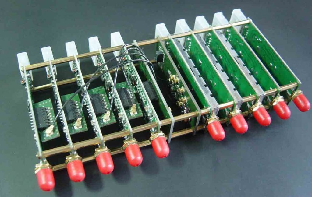
Coherent-receiver.com is a company which is a customer of our RTL-SDR V3 dongle and they have been working on creating a multi-channel coherent receiver product based on the RTL-SDR. An RTL-SDR multi-channel coherent receiver is at its most basic, two or more RTL-SDR dongles (multi-channel) that are running from a single clock source (coherent). A multi-channel coherent receiver allows signal samples from two different antennas to be synchronized against time, allowing for all sorts of interesting applications such as passive radar and direction finding.

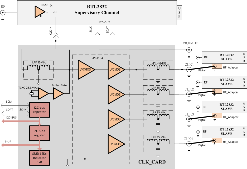
The team at coherent-receiver.com have used the new expansion headers on our V3 dongles to create their product. In their receivers they attach a control board which has a buffered 0.1 PPM TCXO (buffered so it can power multiple RTL-SDR’s). They also added an 8-bit register and I2C connection capabilities which allows for control of future add-on boards. The I2C capability is useful because it means that several RTL-SDR dongles can be controlled and tuned from the same control signal. More information on the registers and build of the receiver control board can be seen on their technical support page.

A ten channel RTL-SDR coherent receiver.
The Coherent Receiver block diagram.

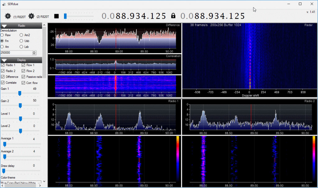
One example application of a multi-channel coherent receiver is passive radar. Coincidentally, we’ve just seen the release of new GUI based Passive Radar software by Dr. Daniel Michał Kamiński in yesterdays post. Passive radar works by listening for strong signals bouncing off airborne objects such as planes and meteors, and performing calculations on the signals being received by two antennas connected to the multi-channel coherent receiver.

A second example is direction finding experiments. By setting up several antennas connected to a multichannel coherent receiver calculations can be made to determine the direction a signal is coming from. An interesting example of direction finding with three coherent RTL-SDRs can be seen in this previous post. A third example application is pulsar detection which we have seen in this previous post

Coherent-receiver.com sent us a prototype unit that they made with four of our V3 dongles. In testing we found that the unit is solidly built and works perfectly. We tested it together with Dr. Kamiński’s passive radar software and it ran well, however we do not have the correct directional antennas required to actually use it as a passive radar yet. In the future we hope to obtain these antennas and test the coherent receiver and the software further.

Currently they do not have pricing for these models as it seems that they are first trying to gauge interest in the product. If you are interested in purchasing or learning more they suggest sending an email to info@coherent-receiver.com. It seems that they are also working on additional RTL-SDR ecosystem products such as filters, downconverters, antennas and LNAs.

We hope that the release of this product and Dr. Kamiński’s software will give a boost to the development of coherent multi-channel receivers as we have not seen much development in this area until recently.

SDRDue running on the coherent-receiver.com unit.

The post A Multi-Channel Coherent RTL-SDR Product: For Passive Radar, Direction Finding and More appeared first on rtl-sdr.com.

Helping to Raise Funds for the Canadian Centre for Experimental Radio Astronomy (CCERA)

$
0
0

Patchvonbraun (aka Marcus Leech) is one of the pioneers in using low cost SDR dongles for amateur radio astronomy experiments. In the past he’s shown us how to receive things like the hydrogen line,  detect meteors and observe solar transits using an RTL-SDR. He’s also given a good overview and introduction to amateur radio astronomy in this slide show.

Now Marcus and others are starting up a new project called the “Canadian Centre for Experimental Radio Astronomy (CCERA)”. They write that this will be an amateur radio astronomy research facility that will produce open source software and hardware designs for small scale amateur radio astronomers. Currently they also already have a hydrogen line telescope set up, which is producing live graphs and data. From their recent posts it also looks like they’re working on building antennas for pulsar detection. They also have a GitHub available for any software they produce at https://github.com/ccera-astro.

Currently CCERA is looking for donations over at gofundme, and they are hoping to eventually raise $25k. They write:

About CCERA:

Radio astronomy is one of the most important ways to observe the cosmos. It is how we learned about the existence of the afterglow of the big bang (the cosmic microwave background), it is how we observe huge swaths of the universe that are otherwise obscured by dust. Most of what’s going on out there can’t be seen with visible light.

Astronomy has traditionally been one of the areas in science where dedicated non-professionals have continued to make an enormous contribution to the field. Optical astronomy requires little more than a telescope and knowledge.

Radio astronomy has, up until recently, required a lot more skill and resources. However, technology has advanced enough that small groups could be making serious contributions to radio astronomy. With the right sorts of software and information, many dedicated non-professionals could be doing good work in the area, and CCERA intends to help make that a reality.

CCERA will be producing open source software and hardware designs to help non-professional and professional radio astronomers alike, documenting them, and helping people get up to speed so that they can use these powerful tools themselves. Our GitHub repository is: https://github.com/ccera-astro

CCERA will also be operating its own radio astronomy facilities, initially in Ontario, Canada. These will serve as a test-bed for our own designs, as a place for us to train interested people in the operation of low cost radio astronomy equipment, and will also be used for real radio astronomy work. All our data will be publically-available.

About us:

Roughly 10 years ago, I and a number of others started a project to restore a large, historic, satellite earth station antenna at Shirleys Bay in Ottawa. Our goal was to bring the dish back on-line for use in amateur radio astronomy, research, and importantly, educational outreach about science, and radio astronomy.

The project came to a sudden end back in 2013/14 when the owner of the dish (The Canadian Space Agency) needed to dismantle it to make way for other occupants of the site.

However, during that period, we became fascinated with the possibilities that opening up radio astronomy to skilled non-professionals could bring.

Since then, our group has been working on another far lower cost project to build our own a specialized radio telescope somewhere in the Rideau Valley area. Many of our group live in the area, and Marcus lives in Smiths Falls. With good attention to the usability of our designs and open publication of our tools under appropriate open source licenses, our work should be replicable by others. We thus hope to kick off a new era in non-professional radio astronomy.

What we need the money for:

We’ve secured a small office in the Gallipeau Center outside of Smiths Falls, and will be able to erect our specialized antenna arrays over the coming year.

While we have a lot of the equipment we’ll need, we’ll have more equipment to buy, and on-going expenses to cover, including rent, insurance, miscellaneous mechanical construction materials (lumber, metal, etc). We also need to cover expenses relating to incorporation as a not-for-profit.

Our goal is to provide a test facility for small-scale radio astronomy research, and to develop techniques that allow small organizations and educational institutions to run their own small-scale radio astronomy observing programs.

If we are successful, in addition to making our designs and software available under open source licenses, we’ll be holding regular public lectures, host training seminars, host school groups, etc. We will also produce videos of our work for those who cannot visit us directly in Ottawa. We want to make some of the techniques of “big science” accessible and understandable.

We can’t do it without the help of the public, who, we hope, will become our students, collaborators, and ongoing supporters.

We will also make all of our data available to the public without fee or restrictions. We believe in openness in scientific endeavours, even small ones such as ours.

Marcus Leech
(tentative) Director
Canadian Centre for Experimental Radio Astronomy
www.ccera.ca

If you have even a passing interest in radio astronomy please consider donating, as CCERA’s work may open up exciting new possibilities for amateur radio astronomers with low cost SDR dongles.

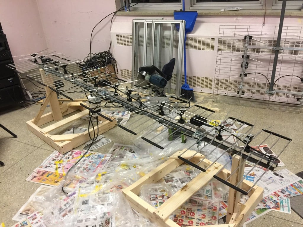
The pulsar antenna being built at CCERA.

The post Helping to Raise Funds for the Canadian Centre for Experimental Radio Astronomy (CCERA) appeared first on rtl-sdr.com.

Searching for giga-Jansky fast radio bursts from the Milky Way with a global array of low-cost radio receivers (RTL-SDRs)

$
0
0

A few days ago a University research paper titled “Searching for giga-Jansky fast radio bursts from the Milky Way with a global array of low-cost radio receivers” was uploaded to the Cornell University Library. In this paper authors Dan Maoz of Tel-Aviv University and Abraham Loeb of Harvard suggest that citizen science enabled mobile phones and RTL-SDR dongles placed around the world could be used to detect fast radio bursts (FRBs) originating from within our own galaxy. The abstract reads:

If fast radio bursts (FRBs) originate from galaxies at cosmological distances, then their all-sky rate implies that the Milky Way may host an FRB on average once every 30-1500 years. If FRBs repeat for decades or centuies, a local FRB could be active now. A typical Galactic FRB would produce a millisecond radio pulse with ~1 GHz flux density of ~3E10 Jy, comparable to the radio flux levels and frequencies of cellular communication devices (cell phones, Wi-Fi, GPS). We propose to search for Galactic FRBs using a global array of low-cost radio receivers. One possibility is to use the ~1GHz communication channel in cellular phones through a Citizens-Science downloadable application. Participating phones would continuously listen for and record candidate FRBs and would periodically upload information to a central data processing website, which correlates the incoming data from all participants, to identify the signature of a real, globe-encompassing, FRB from an astronomical distance. Triangulation of the GPS-based pulse arrival times reported from different locations will provide the FRB sky position, potentially to arc-second accuracy. Pulse arrival times from phones operating at diverse frequencies, or from an on-device de-dispersion search, will yield the dispersion measure (DM) which will indicate the FRB source distance within the Galaxy. A variant of this approach would be to use the built-in ~100 MHz FM-radio receivers present in cell phones for an FRB search at lower frequencies. Alternatively, numerous “software-defined radio” (SDR) devices, costing ~$10 US each, could be plugged into USB ports of personal computers around the world (particularly in radio quiet regions) to establish the global network of receivers.

‘Fast radio bursts’ or FRBs are very brief pulses of extremely strong radio waves which have the transmit power of 500 million suns, though by the time they reach the earth they can only be picked up by radio telescopes. Radio astronomers have so far been mystified by the cause of these FRBs, and research has been hampered by the fact that the source of FRBs is notoriously difficult to pinpoint because they are unpredictable, and their energy appears to originate from all over the sky and not from a single point. Many scientists think that most FRBs must originate from outside of our galaxy, and in 2016 one was finally pinpointed as coming from a dwarf galaxy 2.5 billion light years away from earth. But the authors of the paper speculate from the rate of how often FRBs are seen, that our Milky Way galaxy could host its own local FRB event once every 30 – 1500 years.

If an FRB occurs within our own galaxy then they speculate that the received power could be strong enough to be detected by consumer level mobile phones or RTL-SDR radios, meaning that no large radio telescope dish is required for detection. By continuously monitoring for FRBs on mobile phones and/or RTL-SDRs spread around the world, a local FRB source could one day be pinpointed thanks to the high resolving power of multiple detectors spread apart.

[Also discussed at cfa.harvard.edu/news/2017-07]
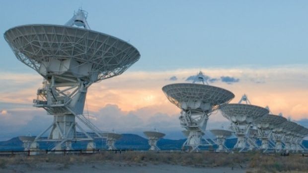
The Very Large Array in Mexico was used to pinpoint an FRB in 2016.
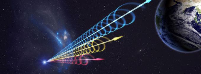
Illustration of an FRB. Certain frequencies arrive faster than others.

The post Searching for giga-Jansky fast radio bursts from the Milky Way with a global array of low-cost radio receivers (RTL-SDRs) appeared first on rtl-sdr.com.


YouTube Videos: NOAA Satellite Tutorial and Building a Radio Telescope

$
0
0

Over on the Thought Emporium YouTube channel the team have uploaded two videos that may be of interest to radio hobbyists. The first video shows a nice overview about receiving NOAA weather satellite images. They explain everything from scratch for complete novice, so the videos are great for almost anyone to watch and learn about radio and SDR concepts. The blurb of the first video reads:

Over the past 2 months, me and my friend Artem have been building antennas to receive signals from weather satellites as they pass overhead. This video chronicles our progress through this project and goes through some of the science involved in working with radio and receiving transmissions. We explore how dipoles work and how to build them, and how we built our final double cross antenna. We used an SDR (software defined radio) called a HackRF to do the work of interpreting the received signals and then decoded them with some special software. We pulled images from 4 satellites: NOAA 15, 18 and 19 as well as METEOR M2. The satellites broadcast immediately as they take the images and no images are stored, so we’re likely the only ones on earth with these images.

https://www.youtube.com/watch?v=cjClTnZ4Xh4

The second video is about building a radio telescope. Like the NOAA video, they explain all concepts in a simple and easy to understand way, so that anyone even without any radio knowledge can understand what the project is about. In the video they also show how they use a 3D printer to create a tracking mount which can point a satellite dish. They then use the dish to create a satellite heat map. The blurb reads:

Over the last 2 months me and my friend Artem (you met him in the last video) built our first radio telescope. It was built mostly out of off the shelf components, like a satellite dish and Ku band LNB, as well as some parts we 3d printed. When all was said and done we had a system that could not only take images of the sky in radio frequencies (in this case 10-12ghz), but could also be used to track satellites. With it, we were able to see the ring of satellites in geosynchronous orbit, over 35,000km away, This is only the first of what I suspect will be many more telescopes like this. Next time we’ll be building ones that are far larger and can see things like the hydrogen lines so we can image the milky way.

https://www.youtube.com/watch?v=aeah3fFYlnA

The post YouTube Videos: NOAA Satellite Tutorial and Building a Radio Telescope appeared first on rtl-sdr.com.

Amateur Pulsar Observations with an RTL-SDR

$
0
0

Back in September 2015 we made a posted that discussed how some amateur radio astronomers have been using RTL-SDR’s for detecting pulsars. A pulsar is a rotating neutron star that emits a beam of electromagnetic radiation. If this beam points towards the earth, it can then be observed with a large dish antenna and a radio, like the RTL-SDR.

In their work they showed how they were able to detect and measure the rotational period of the Vela pulsar, one of the strongest and easiest to receive pulsars. They also noted how using several RTL-SDR dongles could reduce the required satellite dish size.

Recently we came across Hannes Fasching (OE5JFL)’s work where he shows that he has detected 15 pulsars so far using RTL-SDR dongles. His detection system specs include:

Antenna: 7.3m homemade offset dish, OE5JFL tracking system
Feeds: 70cm (424 MHz) dual-dipole with solid reflector, 23cm (1294 MHz) RA3AQ horn
Preamplifiers: 23cm cavity MGF4919, 70cm 2SK571 (30 years old!)
Line Amplifier: PGA103+
Interdigital filter: designed with VK3UM software, 70cm 4-pole, 23cm 3-pole
Receiver: RTL-SDR (error <1ppm), 2 MHz bandwidth
Software: IW5BHY, Presto, Tempo, Murmur

Furthermore, from looking at the Neutron Star Group website, it seems that the majority of amateur radio astronomers interested in pulsar detection are currently using RTL-SDR dongles as the receiver. Some of them have access to very large 25m dishes, but some like IW5BHY, IK5VLS and I0NAA use smaller 2.5m – 5m dishes which can fit into a backyard.

If you are interested in getting into amateur pulsar detection, check out the Neutron Star Group website as they have several resources available for learning.

OE5JFL's 7.3m pulsar detection dish with an RTL-SDR receiver.
OE5JFL’s 7.3m pulsar detection dish with an RTL-SDR receiver.

The post Amateur Pulsar Observations with an RTL-SDR appeared first on rtl-sdr.com.

An Overview of Neutron Star Group Pulsar Detection Projects with the RTL-SDR

$
0
0

Earlier in April we posted about Hannes Fasching (OE5JFL)’s work in detecting pulsars with an RTL-SDR. Thanks to Steve Olney (VK2XV), administrator of the Neutron Star Group for pointing out that there are actually several amateur radio astronomers who are using RTL-SDR dongles for pulsar detection. 

A pulsar is a rotating neutron star that emits a beam of electromagnetic radiation. If this beam points towards the earth, it can then be observed with a large dish antenna and a radio, like the RTL-SDR. Pulsars create weakly detectable noise bursts across a wide frequency range. They create these noise bursts at precise intervals (milliseconds to seconds depending on the pulsar), so they can be detected from within the natural noise by performing some mathematical analysis on the data. Typically a few hours of data needs to be received to be able to analyze it, with more time needed for smaller dishes.


One problem is that pulsar signals can suffer from ‘dispersion’ due to many light years of travel through the interstellar medium. This simply means that higher frequencies of the noise burst tend to arrive before the lower frequencies. Mathematical de-dispersion techniques can be used to eliminate this problem enabling one to take advantage of wideband receivers like the RTL-SDR and other SDRs. The more bandwidth collected and de-dispersed, the smaller the dish required for detection.

Over on the Neutron Star Group several amateur pulsar detection projects are listed, and entries denoted with the “^” symbol make use of the RTL-SDR. Below we show a brief overview of those projects:

Andrea Dell’Immagine (IW5BHY) – Based in Italy Andrea often uses a 3D corner reflector antenna which is equivalent to a 2.5 meter diameter dish to observe pulsars in the 70cm band (~420 MHz). The antenna is in a fixed position so he can only detect pulsars that drift into the beam width of the antenna. With this antenna, a 0.3dB NF LNA, an RTL-SDR and de-dispersion techniques he’s been able to detect the Pulsar B0329+54 which is 2,643 light years away with an integration time of about 3 hours.

Andrea (IW5BHY)'s 3D Corner Reflector Pulsar Detection Antenna.
Andrea (IW5BHY)’s 3D Corner Reflector Pulsar Detection Antenna.

Andrea has also used a 4M dish to detect Pulsar B0329+54 also at 70cm with an RTL-SDR. With the larger dish he’s able to detect it within about 40 minutes of integration time.

Andrea (IW5BHY)'s 4M dish.
Andrea (IW5BHY)’s 4M dish.

Hannes Fasching (OE5JFL) – Based in Austria Hannes has a 7.3M dish that he uses for pulsar detection with his RTL-SDR. With this large dish he’s been able to receive 22 pulsars at both 70cm (424 MHz), and 23cm (1294 MHz) frequencies. With such a large dish, detecting a strong pulsar like B0329+54 only needs less than a minute of integration time.

Mario Natali (I0NAA) – Based in Italy Mario uses a 5M dish to observer pulsars at both 409 MHz and 1297 MHz. Combined with a low noise figure LNA and his RTL-SDR he’s been able to receive the B0329+54 pulsar with an integration time of about 2 – 2.5 hours.

Mario Natali (I0NAA)’s 5M Dish

Michiel Klaassen – From the Dwingeloo Radio Observatory in the Netherlands Michiel has used their large 25M dish and an RTL-SDR to detect B0329+54 at 419 MHz.

Peter East & Guillermo Gancio  Peter and Guillermo have used the large 30M dish at El Instituto Argentino de Radioastronomía (IAR) in Argentina and an RTL-SDR to detect the Vela pulsar (B0833-45) at 1420 MHz.

In terms of hardware required, from the above projects we see that you’ll need an RTL-SDR dongle (other more costly SDR’s could also be used), a dish as large as you can get (along with some sort of dish pointing system), a low noise figure amplifier (0.5dB or less is desired) to be placed right by the dish, a few line amps if the cable run is long and perhaps a filter if you are seeing interference from terrestrial signals.

An overview of software for detecting pulsars with the RTL-SDR can be found over on the Neutron Star Groups software page. Essentially what you need is an analysis program which can work on the raw IQ data that is collected by the RTL-SDR and dish antenna. This software ‘folds’ the data, looking for the regular noise bursts from the pulsars. The output is data that can be used to create a graph indicating the spin period of the pulsar, and thus confirming the detection.

Graph showing the half-period of B0329+54. 350 * 2 = 700 ms which is about what matches on the B0329+54 Wikipedia page.

A Screenshot based Meteor Scatter Detector for HDSDR

$
0
0

Over on our forums Andy (M0CYP) has posted about his new meteor scatter detection program which works with HDSDR and any supported SDR like an RTL-SDR. It works in an interesting way, as instead of analyzing sound files for blips of meteor scatter activity it analyzes screenshots of the HDSDR waterfall. The software automatically grabs the screenshots and determines if a signal is present on any given frequency. You can set a preconfigured detection frequency for a far away transmitter, and if the waterfall shows a reflection it will record that as a meteor.

Meteor scatter works by receiving a distant but powerful transmitter via reflections off the trails of ionized air that meteors leave behind when they enter the atmosphere. Normally the transmitter would be too far away to receive, but if its able to bounce off the ionized trail in the sky it can reach far over the horizon to your receiver. Typically powerful broadcast FM radio stations, analog TV, and radar signals at around 140 MHz are used. Some amateur radio enthusiasts also use this phenomena as a long range VHF communications tool with their own transmitted signals. See the website www.livemeteors.com for a livestream of a permanently set up RTL-SDR meteor detector (although that site does not use Andy’s software).

Andy writes that his meteor scatter detection software is still in beta so there might be some bugs. You can write feedback on the forum post, in the comments here, or contact Andy directly via the link on his website.

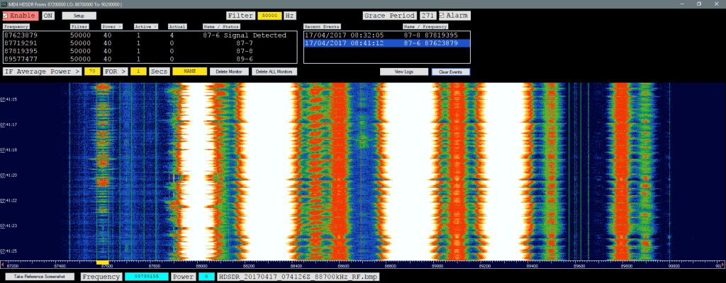
Andy's screenshot based meteor detection software
Andy’s screenshot based meteor detection software

Detecting Pulsars with a Circularly Polarized Yagi and an RTL-SDR

$
0
0

Steve Olney VK2XV is the creator and administrator of the Neutron Star Group website which collects a listing of confirmed amateur attempts at pulsar detection, many of which have been made with a humble RTL-SDR dongle. A pulsar is a rotating neutron star that emits a beam of electromagnetic radiation. If this beam points towards the earth, it can then be observed with a large dish antenna and a radio, like the RTL-SDR.

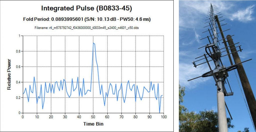
Now after more than four years of trying, Steve has finally been able make his own confirmed pulsar detection by using a 42-elment circularly polarized Yagi antenna tuned for 436 MHz and an RTL-SDR. Typically a large dish antenna is used to receive a pulsar, but Steve has instead used a fixed position circularly polarized Yagi antenna, which he writes has an equivalent aperture to a 2.8 meter diameter dish. His antenna can point directly upwards as his target is the Vela pulsar which happens to pass almost directly overhead at his location.

Detection of a pulsar involves determining its rotational period from the regular wideband noise pulses that they produce. Pulsar detections with large aperture dish antennas can easily be confirmed due to high SNR, but smaller weaker detectors require some use of some mathematical techniques to confirm a positive detection. This is especially important as it’s possible for terrestrial signals to mimic a pulsar. 

In order to detect and confirm the pulsar detection from a weak signal, Steve uses a technique called epoch folding, which makes use of the fact that the period of pulsar pulses are extremely regular. To verify the results he also makes use of techniques such as folding at the predicted period, de-dispersion and plotting daily results against the predicted results. These techniques are explained in more depth in his results post.

Steve's Results showing the detected pulsar period and his CP Yagi Antenna
Steve’s Results showing the detected pulsar period and his CP Yagi Antenna
Viewing all 113 articles
Browse latest View live