Over on YouTube user MaskitolSAE has uploaded a video showing him receiving some noise bursts from Jupiter with his SDRplay RSP1. The planet Jupiter is known to emit bursts of noise via natural ‘radio lasers’ powered partly by the planets interaction with the electrically conductive gases emitted by Io, one of the the planets moons. When Jupiter is high in the sky and the Earth passes through one of these radio lasers the noise bursts can be received on Earth quite easily with an appropriate antenna
In his video MaskitolSAE shows the 10 MHz of waterfall and audio from some Jupiter noise bursts received with his SDRplay RSP1 at 22119 kHz. According to the YouTube description, it appears that he is using the UTR-2 radio telescope which is a large Ukrainian radio telescope installation that consists of an array of 2040 dipoles. A professional radio telescope installation is not required to receive the Jupiter bursts (a backyard dipole tuned to ~20 MHz will work), but the professional radio telescope does get some really nice strong bursts as seen in the video.
Over on his blog Dave Venne has been documenting his attempts at using National Weather Service (NWS) broadcasts for forward scatter meteor detection with an RTL-SDR. Forward scatter meteor detection is a passive method for detecting meteors as they enter the atmosphere. When a meteor enters the atmosphere it leaves behind a trail of highly RF reflective ionized air. This ionized air can reflect far away signals from strong transmitters directly into your receiving antenna, thus detecting a meteor.
Typically signals from analog TV and broadcast FM stations are preferred as they are near the optimal frequency for reflection of the ionized trails. However, Dave lives in an area where the broadcast FM spectrum is completely saturated with signals, leaving no empty frequencies to detect meteors. Instead Dave decided to try and use NWS signals at 160 MHz. In the USA there are seven frequencies for NWS and they are physically spaced out so that normally only one transmitter can be heard. Thus tuning to a far away station should produce nothing but static unless a meteor is reflecting its signal. Dave however does note that the 160 MHz frequency is less than optimal for detection and you can expect about 14 dB less reflected signal from meteors.
So far Dave has been able to detect several ‘blips’ with his cross-dipole antenna, RTL-SDR and SDR#. He also uses the Chronolapse freeware software to perform timelapse screenshots of the SDR# waterfall, so that the waterfall can be reviewed later. Unfortunately, most of the blips appear to have been aircraft as they seem to coincide with local air activity, and exhibit a Doppler shift characteristic that is typical of aircraft. He notes that the idea may still work for others who do not live near an airport.
A possible meteor detection in SDR#.Aircraft detection doppler
We note that if you are interested in detecting aircraft via passive forward scatter and their Doppler patterns, then this previous post on just that may interest you.
Hydrogen atoms randomly emit photons at a wavelength of 21cm (1420.4058 MHz). Normally a single hydrogen atom will only very rarely emit a photon, but since space and the galaxy is filled with many hydrogen atoms the average effect is an observable RF power spike at 1420.4058 MHz. By pointing a radio telescope at the night sky and integrating the RF power over time, a power spike indicating the hydrogen line can be observed in a frequency spectrum plot. This can be used for some interesting experiments, for example you could measure the size and shape of our galaxy. Thicker areas of the galaxy will have more hydrogen and thus a larger spike.
In his tutorial Adam discusses important technical points such as noise figure and filtering. Essentially, when trying to receive the hydrogen line you need a system with a low noise figure and good filtering. The RTL-SDR has a fairly poor noise figure of about 6dB at 1420MHz. But it turns out that the first amplifier element in the receive chain is the one that dominates the noise figure value. So by placing an LNA with a low noise figure right by the antenna, the system noise figure can be brought down to about 1dB, and losses in coax and filters become negligible as well. At the end of the tutorial he also discusses some supplementary points such as ESD protection, bias tees and IP3.
One note from us is that Adam writes that the RTL-SDR V3 bias tee can only provide 50mA, but it can actually provide up to 200mA continuously assuming the host can provide it (keep the dongle in a cool shaded area though). Most modern USB 2.0 and USB3.0 ports on PCs should have no problem providing up to 1A or more. We’ve also tested the LP5907 based Airspy bias tee at up to 150mA without trouble, so the 50mA rating is probably quite conservative. So these bias tee options should be okay for powering 2xLNA4ALL.
Finally Adam writes that in the future he will write a paper discussing homebrew hydrogen line antennas which should complete the tutorial allowing anyone to build a cheap hydrogen line radio telescope.
One configuration with 2xLNA4ALL, 1x interstage filter, and 1x recceiver side filter with bias tee.
Back in September 2015 we made a posted that discussed how some amateur radio astronomers have been using RTL-SDR’s for detecting pulsars. A pulsar is a rotating neutron star that emits a beam of electromagnetic radiation. If this beam points towards the earth, it can then be observed with a large dish antenna and a radio, like the RTL-SDR.
In their work they showed how they were able to detect and measure the rotational period of the Vela pulsar, one of the strongest and easiest to receive pulsars. They also noted how using several RTL-SDR dongles could reduce the required satellite dish size.
Antenna: 7.3m homemade offset dish, OE5JFL tracking system Feeds: 70cm (424 MHz) dual-dipole with solid reflector, 23cm (1294 MHz) RA3AQ horn Preamplifiers: 23cm cavity MGF4919, 70cm 2SK571 (30 years old!) Line Amplifier: PGA103+ Interdigital filter: designed with VK3UM software, 70cm 4-pole, 23cm 3-pole Receiver: RTL-SDR (error <1ppm), 2 MHz bandwidth Software: IW5BHY, Presto, Tempo, Murmur
Furthermore, from looking at the Neutron Star Group website, it seems that the majority of amateur radio astronomers interested in pulsar detection are currently using RTL-SDR dongles as the receiver. Some of them have access to very large 25m dishes, but some like IW5BHY, IK5VLS and I0NAA use smaller 2.5m – 5m dishes which can fit into a backyard.
If you are interested in getting into amateur pulsar detection, check out the Neutron Star Group website as they have several resources available for learning.
OE5JFL’s 7.3m pulsar detection dish with an RTL-SDR receiver.
Earlier in April we posted about Hannes Fasching (OE5JFL)’s work in detecting pulsars with an RTL-SDR. Thanks to Steve Olney (VK2XV), administrator of the Neutron Star Group for pointing out that there are actually several amateur radio astronomers who are using RTL-SDR dongles for pulsar detection.
A pulsar is a rotating neutron star that emits a beam of electromagnetic radiation. If this beam points towards the earth, it can then be observed with a large dish antenna and a radio, like the RTL-SDR. Pulsars create weakly detectable noise bursts across a wide frequency range. They create these noise bursts at precise intervals (milliseconds to seconds depending on the pulsar), so they can be detected from within the natural noise by performing some mathematical analysis on the data. Typically a few hours of data needs to be received to be able to analyze it, with more time needed for smaller dishes.
One problem is that pulsar signals can suffer from ‘dispersion’ due to many light years of travel through the interstellar medium. This simply means that higher frequencies of the noise burst tend to arrive before the lower frequencies. Mathematical de-dispersion techniques can be used to eliminate this problem enabling one to take advantage of wideband receivers like the RTL-SDR and other SDRs. The more bandwidth collected and de-dispersed, the smaller the dish required for detection.
Over on the Neutron Star Group several amateur pulsar detection projects are listed, and entries denoted with the “^” symbol make use of the RTL-SDR. Below we show a brief overview of those projects:
Andrea Dell’Immagine (IW5BHY)– Based in Italy Andrea often uses a 3D corner reflector antenna which is equivalent to a 2.5 meter diameter dish to observe pulsars in the 70cm band (~420 MHz). The antenna is in a fixed position so he can only detect pulsars that drift into the beam width of the antenna. With this antenna, a 0.3dB NF LNA, an RTL-SDR and de-dispersion techniques he’s been able to detect the Pulsar B0329+54 which is 2,643 light years away with an integration time of about 3 hours.
Andrea (IW5BHY)’s 3D Corner Reflector Pulsar Detection Antenna.
Hannes Fasching (OE5JFL) – Based in Austria Hannes has a 7.3M dish that he uses for pulsar detection with his RTL-SDR. With this large dish he’s been able to receive 22 pulsars at both 70cm (424 MHz), and 23cm (1294 MHz) frequencies. With such a large dish, detecting a strong pulsar like B0329+54 only needs less than a minute of integration time.
Mario Natali (I0NAA) – Based in Italy Mario uses a 5M dish to observer pulsars at both 409 MHz and 1297 MHz. Combined with a low noise figure LNA and his RTL-SDR he’s been able to receive the B0329+54 pulsar with an integration time of about 2 – 2.5 hours.
Mario Natali (I0NAA)’s 5M Dish
Michiel Klaassen – From the Dwingeloo Radio Observatory in the Netherlands Michiel has used their large 25M dish and an RTL-SDR to detect B0329+54 at 419 MHz.
Peter East & Guillermo Gancio–Peter and Guillermo have used the large 30M dish at El Instituto Argentino de Radioastronomía (IAR) in Argentina and an RTL-SDR to detect the Vela pulsar (B0833-45) at 1420 MHz.
In terms of hardware required, from the above projects we see that you’ll need an RTL-SDR dongle (other more costly SDR’s could also be used), a dish as large as you can get (along with some sort of dish pointing system), a low noise figure amplifier (0.5dB or less is desired) to be placed right by the dish, a few line amps if the cable run is long and perhaps a filter if you are seeing interference from terrestrial signals.
An overview of software for detecting pulsars with the RTL-SDR can be found over on the Neutron Star Groups software page. Essentially what you need is an analysis program which can work on the raw IQ data that is collected by the RTL-SDR and dish antenna. This software ‘folds’ the data, looking for the regular noise bursts from the pulsars. The output is data that can be used to create a graph indicating the spin period of the pulsar, and thus confirming the detection.
Graph showing the half-period of B0329+54. 350 * 2 = 700 ms which is about what matches on the B0329+54 Wikipedia page.
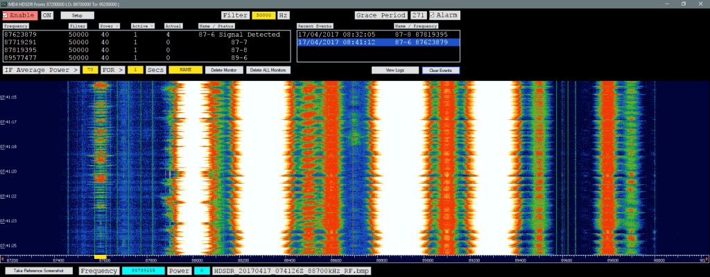
Over on our forums Andy (M0CYP) has posted about his new meteor scatter detection program which works with HDSDR and any supported SDR like an RTL-SDR. It works in an interesting way, as instead of analyzing sound files for blips of meteor scatter activity it analyzes screenshots of the HDSDR waterfall. The software automatically grabs the screenshots and determines if a signal is present on any given frequency. You can set a preconfigured detection frequency for a far away transmitter, and if the waterfall shows a reflection it will record that as a meteor.
Meteor scatter works by receiving a distant but powerful transmitter via reflections off the trails of ionized air that meteors leave behind when they enter the atmosphere. Normally the transmitter would be too far away to receive, but if its able to bounce off the ionized trail in the sky it can reach far over the horizon to your receiver. Typically powerful broadcast FM radio stations, analog TV, and radar signals at around 140 MHz are used. Some amateur radio enthusiasts also use this phenomena as a long range VHF communications tool with their own transmitted signals. See the website www.livemeteors.com for a livestream of a permanently set up RTL-SDR meteor detector (although that site does not use Andy’s software).
Andy writes that his meteor scatter detection software is still in beta so there might be some bugs. You can write feedback on the forum post, in the comments here, or contact Andy directly via the link on his website.
Steve Olney VK2XV is the creator and administrator of the Neutron Star Group website which collects a listing of confirmed amateur attempts at pulsar detection, many of which have been made with a humble RTL-SDR dongle. A pulsar is a rotating neutron star that emits a beam of electromagnetic radiation. If this beam points towards the earth, it can then be observed with a large dish antenna and a radio, like the RTL-SDR.
Now after more than four years of trying, Steve has finally been able make his own confirmed pulsar detection by using a 42-elment circularly polarized Yagi antenna tuned for 436 MHz and an RTL-SDR. Typically a large dish antenna is used to receive a pulsar, but Steve has instead used a fixed position circularly polarized Yagi antenna, which he writes has an equivalent aperture to a 2.8 meter diameter dish. His antenna can point directly upwards as his target is the Vela pulsar which happens to pass almost directly overhead at his location.
Detection of a pulsar involves determining its rotational period from the regular wideband noise pulses that they produce. Pulsar detections with large aperture dish antennas can easily be confirmed due to high SNR, but smaller weaker detectors require some use of some mathematical techniques to confirm a positive detection. This is especially important as it’s possible for terrestrial signals to mimic a pulsar.
In order to detect and confirm the pulsar detection from a weak signal, Steve uses a technique called epoch folding, which makes use of the fact that the period of pulsar pulses are extremely regular. To verify the results he also makes use of techniques such as folding at the predicted period, de-dispersion and plotting daily results against the predicted results. These techniques are explained in more depth in his results post.
Steve’s Results showing the detected pulsar period and his CP Yagi Antenna
Over on YouTube user MaskitolSAE has uploaded a video showing him receiving some noise bursts from Jupiter with his SDRplay RSP1. The planet Jupiter is known to emit bursts of noise via natural ‘radio lasers’ powered partly by the planets interaction with the electrically conductive gases emitted by Io, one of the the planets moons. When Jupiter is high in the sky and the Earth passes through one of these radio lasers the noise bursts can be received on Earth quite easily with an appropriate antenna
In his video MaskitolSAE shows the 10 MHz of waterfall and audio from some Jupiter noise bursts received with his SDRplay RSP1 at 22119 kHz. According to the YouTube description, it appears that he is using the UTR-2 radio telescope which is a large Ukrainian radio telescope installation that consists of an array of 2040 dipoles. A professional radio telescope installation is not required to receive the Jupiter bursts (a backyard dipole tuned to ~20 MHz will work), but the professional radio telescope does get some really nice strong bursts as seen in the video.
Over on his blog Dave Venne has been documenting his attempts at using National Weather Service (NWS) broadcasts for forward scatter meteor detection with an RTL-SDR. Forward scatter meteor detection is a passive method for detecting meteors as they enter the atmosphere. When a meteor enters the atmosphere it leaves behind a trail of highly RF reflective ionized air. This ionized air can reflect far away signals from strong transmitters directly into your receiving antenna, thus detecting a meteor.
Typically signals from analog TV and broadcast FM stations are preferred as they are near the optimal frequency for reflection of the ionized trails. However, Dave lives in an area where the broadcast FM spectrum is completely saturated with signals, leaving no empty frequencies to detect meteors. Instead Dave decided to try and use NWS signals at 160 MHz. In the USA there are seven frequencies for NWS and they are physically spaced out so that normally only one transmitter can be heard. Thus tuning to a far away station should produce nothing but static unless a meteor is reflecting its signal. Dave however does note that the 160 MHz frequency is less than optimal for detection and you can expect about 14 dB less reflected signal from meteors.
So far Dave has been able to detect several ‘blips’ with his cross-dipole antenna, RTL-SDR and SDR#. He also uses the Chronolapse freeware software to perform timelapse screenshots of the SDR# waterfall, so that the waterfall can be reviewed later. Unfortunately, most of the blips appear to have been aircraft as they seem to coincide with local air activity, and exhibit a Doppler shift characteristic that is typical of aircraft. He notes that the idea may still work for others who do not live near an airport.
A possible meteor detection in SDR#.Aircraft detection doppler
We note that if you are interested in detecting aircraft via passive forward scatter and their Doppler patterns, then this previous post on just that may interest you.
Hydrogen atoms randomly emit photons at a wavelength of 21cm (1420.4058 MHz). Normally a single hydrogen atom will only very rarely emit a photon, but since space and the galaxy is filled with many hydrogen atoms the average effect is an observable RF power spike at 1420.4058 MHz. By pointing a radio telescope at the night sky and integrating the RF power over time, a power spike indicating the hydrogen line can be observed in a frequency spectrum plot. This can be used for some interesting experiments, for example you could measure the size and shape of our galaxy. Thicker areas of the galaxy will have more hydrogen and thus a larger spike.
In his tutorial Adam discusses important technical points such as noise figure and filtering. Essentially, when trying to receive the hydrogen line you need a system with a low noise figure and good filtering. The RTL-SDR has a fairly poor noise figure of about 6dB at 1420MHz. But it turns out that the first amplifier element in the receive chain is the one that dominates the noise figure value. So by placing an LNA with a low noise figure right by the antenna, the system noise figure can be brought down to about 1dB, and losses in coax and filters become negligible as well. At the end of the tutorial he also discusses some supplementary points such as ESD protection, bias tees and IP3.
One note from us is that Adam writes that the RTL-SDR V3 bias tee can only provide 50mA, but it can actually provide up to 200mA continuously assuming the host can provide it (keep the dongle in a cool shaded area though). Most modern USB 2.0 and USB3.0 ports on PCs should have no problem providing up to 1A or more. We’ve also tested the LP5907 based Airspy bias tee at up to 150mA without trouble, so the 50mA rating is probably quite conservative. So these bias tee options should be okay for powering 2xLNA4ALL.
Finally Adam writes that in the future he will write a paper discussing homebrew hydrogen line antennas which should complete the tutorial allowing anyone to build a cheap hydrogen line radio telescope.
One configuration with 2xLNA4ALL, 1x interstage filter, and 1x recceiver side filter with bias tee.
If you are in Europe you can also make use of the Graves radar simply by tuning to its frequency of 143.050 MHz and listening for reflections of its signal bouncing off things like meteors, planes and spacecraft. Since Graves points its signal upwards, it’s unlikely that you’ll directly receive the signal straight from the antenna, instead you’ll only see the reflections from objects.
DK8OK also explains in his post how you can use SDR-Console V3 to create a level diagram which shows power vs time, allowing you to count reflections and visualize the response of the reflection.
Any SDR that can tune to VHF frequencies such an an RTL-SDR can be used for monitoring reflections like this. If you aren’t in Europe you might consider looking for distant strong transmitters such as for TV/FM which you could also monitor for reflections.
Graves reflection of a meteor trail visualized in SDR-Console V3.
Thanks to Wolfgang Kaufmann for submitting news about his new software called ‘Meteor Logger’. This tool can be used to count the number of meteors entering the atmosphere which have been detected by a meteor scatter setup using an RTL-SDR or similar SDR.
Wolfgang writes about his software:
I have developed a new piece of software “Meteor Logger” to detect and log radio meteors from the digital audio stream of a PC-soundcard. It is based on Python 3. It is addressed to those meteor enthusiasts who want get the most information out of forward scattering of radio waves off meteor trails. “Meteor Logger” do not display spectrograms, it delivers an instantaneous and continuous numerical output of the detected signal with a high time resolution of about 11 ms. Thereby a radio meteor signal is not detected on the basis of an amplitude threshold but on its signature in the frequency domain. “Meteor Logger” has a built in auto notch function that may be helpful in case of a persistent strong interference line. From these data not only hourly count rates can be derived but it is also possible to easily study power profiles of meteors as well as Doppler shifts of head echoes.
As receiving front end a RTL-SDR is fine, if you strive after a very high signal resolution you may use a Funcube Dongle Pro. I employed SDR# to run the RTL-SDR. GRAVES-radar is used as transmitter. The added screenshot shows this setup together with “Meteor Logger”.
Additionally I wrote an also Python 3 based post processing software “Process Data” that allows for clearing the raw data, viewing and analysing them and exporting them in different ways (e.g. as RMOB-file for opening with “Cologramme Lab” of Pierre Terrier, see added screenshot).
Meteor scatter works by receiving a distant but powerful transmitter via reflections off the trails of ionized air that meteors leave behind when they enter the atmosphere. Normally the transmitter would be too far away to receive, but if its able to bounce off the ionized trail in the sky it can reach far over the horizon to your receiver. Typically powerful broadcast FM radio stations, analog TV, and radar signals at around 140 MHz are used. Some amateur radio enthusiasts also use this phenomena as a long range VHF communications tool with their own transmitted signals. See the website www.livemeteors.com for a livestream of a permanently set up RTL-SDR meteor detector.
Hydrogen tends to emit radio signals in the 21cm (1.4 GHz) region of the frequency spectrum. An emission from a single Hydrogen atom is very rare, but since there is so much Hydrogen in space a bump at 1.4 GHz can be observed on the frequency spectrum if a sensitive radio is used with a directional antenna pointing up at the sky. This is a moderate difficulty experiment that can be performed by amateur radio astronomers today with cheap RTL-SDRs or other SDRs together with some LNAs.
The astronomers in this experiment focus on a distortion in the 21cm line signal that is expected to have been created when the first stars formed. The their paper they write:
After stars formed in the early Universe, their ultraviolet light is expected, eventually, to have penetrated the primordial hydrogen gas and altered the excitation state of its 21-centimetre hyperfine line. This alteration would cause the gas to absorb photons from the cosmic microwave background, producing a spectral distortion that should be observable today at radio frequencies of less than 200 megahertz.
The results show a successful detection of the expected phenomena at 78 MHz, confirming the age at when the first stars have been predicted to have begun forming. The phenomena is detected at 78 MHz instead of 1.4 GHz because the wavelength of a Hydrogren line signal gets stretched the further the source is from us, due to the redshift doppler effect from the expansion of the Universe. This detection is from some of the furthest (and thus oldest) stars in the Universe, so a big stretch is expected.
The experiment consisted of a broadband blade dipole which was set up in the Australian outback. Since the cosmic signal is expected to be detected right in the middle of the broadcast FM band, a dedicated radio-quiet location is required to stand any chance of detection. The receiving SDR hardware consists of an LNA, line amp, filtering and a 14-bit ADC that is connected to a PC.
It seems possible that this experiment could be repeated by amateur radio astronomers with commercial SDR hardware, but the biggest challenge would probably be finding a very radio-quiet location without broadcast FM radio signals.
The 78 MHz Cosmic Signal SDR Detection SetupDipole antenna with 30mx30m ground plane
Steve Olney VK2XV is the creator and administrator of the Neutron Star Group website which collects a listing of confirmed amateur attempts at pulsar detection, many of which have been made with a humble RTL-SDR dongle. A pulsar is a rotating neutron star that emits a beam of electromagnetic radiation. If this beam points towards the earth, it can then be observed with a large dish antenna and a radio, like the RTL-SDR.
Now after more than four years of trying, Steve has finally been able make his own confirmed pulsar detection by using a 42-elment circularly polarized Yagi antenna tuned for 436 MHz and an RTL-SDR. Typically a large dish antenna is used to receive a pulsar, but Steve has instead used a fixed position circularly polarized Yagi antenna, which he writes has an equivalent aperture to a 2.8 meter diameter dish. His antenna can point directly upwards as his target is the Vela pulsar which happens to pass almost directly overhead at his location.
Detection of a pulsar involves determining its rotational period from the regular wideband noise pulses that they produce. Pulsar detections with large aperture dish antennas can easily be confirmed due to high SNR, but smaller weaker detectors require some use of some mathematical techniques to confirm a positive detection. This is especially important as it’s possible for terrestrial signals to mimic a pulsar.
In order to detect and confirm the pulsar detection from a weak signal, Steve uses a technique called epoch folding, which makes use of the fact that the period of pulsar pulses are extremely regular. To verify the results he also makes use of techniques such as folding at the predicted period, de-dispersion and plotting daily results against the predicted results. These techniques are explained in more depth in his results post.
Steve’s Results showing the detected pulsar period and his CP Yagi Antenna
Over on YouTube user MaskitolSAE has uploaded a video showing him receiving some noise bursts from Jupiter with his SDRplay RSP1. The planet Jupiter is known to emit bursts of noise via natural ‘radio lasers’ powered partly by the planets interaction with the electrically conductive gases emitted by Io, one of the the planets moons. When Jupiter is high in the sky and the Earth passes through one of these radio lasers the noise bursts can be received on Earth quite easily with an appropriate antenna
In his video MaskitolSAE shows the 10 MHz of waterfall and audio from some Jupiter noise bursts received with his SDRplay RSP1 at 22119 kHz. According to the YouTube description, it appears that he is using the UTR-2 radio telescope which is a large Ukrainian radio telescope installation that consists of an array of 2040 dipoles. A professional radio telescope installation is not required to receive the Jupiter bursts (a backyard dipole tuned to ~20 MHz will work), but the professional radio telescope does get some really nice strong bursts as seen in the video.
Over on his blog Dave Venne has been documenting his attempts at using National Weather Service (NWS) broadcasts for forward scatter meteor detection with an RTL-SDR. Forward scatter meteor detection is a passive method for detecting meteors as they enter the atmosphere. When a meteor enters the atmosphere it leaves behind a trail of highly RF reflective ionized air. This ionized air can reflect far away signals from strong transmitters directly into your receiving antenna, thus detecting a meteor.
Typically signals from analog TV and broadcast FM stations are preferred as they are near the optimal frequency for reflection of the ionized trails. However, Dave lives in an area where the broadcast FM spectrum is completely saturated with signals, leaving no empty frequencies to detect meteors. Instead Dave decided to try and use NWS signals at 160 MHz. In the USA there are seven frequencies for NWS and they are physically spaced out so that normally only one transmitter can be heard. Thus tuning to a far away station should produce nothing but static unless a meteor is reflecting its signal. Dave however does note that the 160 MHz frequency is less than optimal for detection and you can expect about 14 dB less reflected signal from meteors.
So far Dave has been able to detect several ‘blips’ with his cross-dipole antenna, RTL-SDR and SDR#. He also uses the Chronolapse freeware software to perform timelapse screenshots of the SDR# waterfall, so that the waterfall can be reviewed later. Unfortunately, most of the blips appear to have been aircraft as they seem to coincide with local air activity, and exhibit a Doppler shift characteristic that is typical of aircraft. He notes that the idea may still work for others who do not live near an airport.
A possible meteor detection in SDR#.Aircraft detection doppler
We note that if you are interested in detecting aircraft via passive forward scatter and their Doppler patterns, then this previous post on just that may interest you.
Hydrogen atoms randomly emit photons at a wavelength of 21cm (1420.4058 MHz). Normally a single hydrogen atom will only very rarely emit a photon, but since space and the galaxy is filled with many hydrogen atoms the average effect is an observable RF power spike at 1420.4058 MHz. By pointing a radio telescope at the night sky and integrating the RF power over time, a power spike indicating the hydrogen line can be observed in a frequency spectrum plot. This can be used for some interesting experiments, for example you could measure the size and shape of our galaxy. Thicker areas of the galaxy will have more hydrogen and thus a larger spike.
In his tutorial Adam discusses important technical points such as noise figure and filtering. Essentially, when trying to receive the hydrogen line you need a system with a low noise figure and good filtering. The RTL-SDR has a fairly poor noise figure of about 6dB at 1420MHz. But it turns out that the first amplifier element in the receive chain is the one that dominates the noise figure value. So by placing an LNA with a low noise figure right by the antenna, the system noise figure can be brought down to about 1dB, and losses in coax and filters become negligible as well. At the end of the tutorial he also discusses some supplementary points such as ESD protection, bias tees and IP3.
One note from us is that Adam writes that the RTL-SDR V3 bias tee can only provide 50mA, but it can actually provide up to 200mA continuously assuming the host can provide it (keep the dongle in a cool shaded area though). Most modern USB 2.0 and USB3.0 ports on PCs should have no problem providing up to 1A or more. We’ve also tested the LP5907 based Airspy bias tee at up to 150mA without trouble, so the 50mA rating is probably quite conservative. So these bias tee options should be okay for powering 2xLNA4ALL.
Finally Adam writes that in the future he will write a paper discussing homebrew hydrogen line antennas which should complete the tutorial allowing anyone to build a cheap hydrogen line radio telescope.
One configuration with 2xLNA4ALL, 1x interstage filter, and 1x recceiver side filter with bias tee.
If you are in Europe you can also make use of the Graves radar simply by tuning to its frequency of 143.050 MHz and listening for reflections of its signal bouncing off things like meteors, planes and spacecraft. Since Graves points its signal upwards, it’s unlikely that you’ll directly receive the signal straight from the antenna, instead you’ll only see the reflections from objects.
DK8OK also explains in his post how you can use SDR-Console V3 to create a level diagram which shows power vs time, allowing you to count reflections and visualize the response of the reflection.
Any SDR that can tune to VHF frequencies such an an RTL-SDR can be used for monitoring reflections like this. If you aren’t in Europe you might consider looking for distant strong transmitters such as for TV/FM which you could also monitor for reflections.
Graves reflection of a meteor trail visualized in SDR-Console V3.
A corner reflector antenna is basically a monopole antenna with a metallic 'corner' reflector placed behind it. The reflector helps the monopole collect signals over a wider aperture resulting in signals coming in stronger from the direction that the corner is pointing at. In past posts we've seen a homemade tinfoil corner reflector used to improve reception of the generic stock RTL-SDR monopole antenna, and a larger one was used in a radio astronomy experiment to detect a pulsar with an RTL-SDR.
Recently The Thought Emporium YouTube channel has uploaded a video showing how to build a large 2 meter 3D corner reflector out of readily available metal conduit pipes and chicken wire. While the antenna has not been tested yet, they hope to be able to use it to receive weather satellite images from GOES-16, to receive moon bounce signals, to map the Hydrogen line and to detect pulsars.
Building a Giant 2m Corner Reflector Antenna For Less than $200 (For Goes-16, Pulsars and More!)
Thanks to IU2EFA (William) for writing in and letting us know about his success in decoding telemetry from the moon orbiting satellite known as DSLWP-B / LONGJIANG-2. LONJIANG-2 is a Chinese lunar microsatellite (45kg) that was launched in May 2018. It is designed to perform ultra long-wave radio astronomy observations. It also has an on board camera and took some nice photos of the Earth back in June.
While the satellite is still being tested, William notes that it is transmitting telemetry data to Earth during it's scheduled days at 435.4 MHz and 436.4 MHz, and the signal can be received with an RTL-SDR and Yagi antenna. William writes:
[LONJIAN-2] transmits with a little linear antenna and a little power of just 2 Watts.
In other sessions, I used a professional radio to have the maximum performance.
But this morning I wanted to test the reception, just using my RTLSDR V3 and my antenna yagi 15 elements pointed to the Moon. No other options (as filters, pre aplifiers, or other stuffs. Zero of these)
Well, the result was great. I received the signals and also i could decode them!
So I think people can be happy to know, that with a very little setup, they can receive incredible little signals from great distances.
When I received these signals, the Moon distance was about 378500 km.
LONGJIAN-2 transmits telemetry with GMSK and JT4G, and JT4G can be decoded with WSJT-X or WSJT 10. There is also a GNU Radio program called gr-dslwp that can be used to decode the telemetry. JT4G is a weak signal coding that can be decoded with signal levels down to -17 dB. Therefore anyone with modest hardware can decode the satellite. More information about the coding can be found on this post by Daniel Estevez.
On the Lilacsat page for LONGJIANG-2 if you scroll down you can also see reports from several other amateur radio operators who have managed to receive the satellite with RTL-SDR dongles and other radios. Below is an image of an example for SP5ULN who was able to receive and decode the JT4G signal with an RTL-SDR, LNA, and 19-element Yagi.
Example of LONJIAN-2 being received with an RTL-SDR by SP5ULN as noted on the LilacSat website.